By John Oden
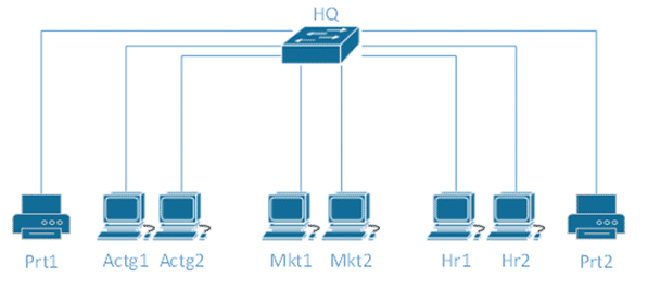
Early on in your journey into the world of networking, you probably learned about a Local Area Network, or LAN. A LAN is a collection of devices, all typically located in close proximity, with connectivity from one device to another. Figure 1 shows a LAN for an organization with several departments.
 Figure 1 A Typical Local Area Network (LAN)
Issues with LANs
This arrangement gets the job done in that each device can communicate with any other device, but as the size of the network grows, several problems will occur. What if the organization’s security policy dictates that sensitive data on computers in the Accounting department should not be accessible by other departments? In this design, we have no easy way to enforce that policy.
Another problem that will occur as this network grows is excessive broadcast traffic. Do the computers in the Marketing department really need to process network broadcasts that occur when computers in the Accounting and Human Resources departments attempt to communicate with the printers? No they don’t, but in this design, we have no way to isolate broadcast traffic.
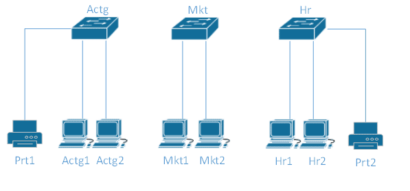
 Figure 2 Multiple LANs
One approach to resolving these issues would be to divide our network into multiple LANs, as shown in Figure 2. By connecting the devices in each department to their own switch, we have created additional broadcast domains that isolate broadcast traffic within each department. We have also addressed security concerns by making sure that computers in one department cannot access sensitive data in another department. We may have addressed our security concerns a little too well, because now computers in one department can never access computers in another department and the folks in the Marketing department cannot access a printer. That’s not ideal either. Notice also that we now would have to purchase, install, and maintain three separate pieces of hardware where one might do the job.
Introducing the VLAN
A solution to these and other problems is the Virtual Local Area Network, or VLAN. VLAN technology is included in the feature sets of most modern Ethernet switches. A VLAN behaves just like a LAN in all respects but with additional flexibility. By using VLAN technology, it is possible to subdivide a single physical switch into several logical switches. VLANs are implemented by using the appropriate switch configuration commands to create the VLANs and assign specific switch interfaces to the desired VLAN.

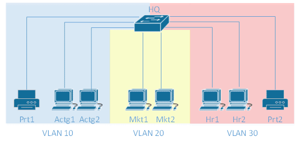
Figure 3 A VLAN Implementation
In Figure 3 we see a network in which VLANs have been implemented. This network is logically equivalent to the network shown in Figure 2, but only one physical switch is required. Switch interfaces for devices in the Accounting department have been assigned to VLAN 10, devices in the Marketing department are connected to switch interfaces in VLAN 20, and the HR department uses VLAN 30.
Switches implement VLANs by adding a VLAN tag to the Ethernet frames as they enter the switch. The VLAN tag contains the VLAN ID and other information, which is determined by the interface from which the frame enters the switch. The switch uses VLAN tags to ensure that each Ethernet frame is confined to the VLAN to which it belongs based on the VLAN ID contained in the VLAN tag. The VLAN tags are removed as the frames exit the switch on the way to their destination.
Here is the configuration of a Cisco Catalyst 2960 switch that produces the VLAN configuration shown in Figure 3:
vlan 10 name Actg
vlan 20 name Mkt
vlan 30 name Hr
!
interface FastEthernet0/1
switchport access vlan 10
switchport mode access
!
interface FastEthernet0/2
switchport access vlan 10
switchport mode access
!
interface FastEthernet0/3
switchport access vlan 10
switchport mode access
!
interface FastEthernet0/4
switchport access vlan 20
switchport mode access
!
interface FastEthernet0/5
switchport access vlan 20
switchport mode access
!
interface FastEthernet0/6
switchport access vlan 30
switchport mode access
!
interface FastEthernet0/7
switchport access vlan 30
switchport mode access
!
interface FastEthernet0/8
switchport access vlan 30
switchport mode access
Figure 4 VLAN Configuration
First, the VLANs are created by the vlan vlan-id name name command. Next, the switchport access vlan vlan-id command is applied to each interface in interface configuration mode to assign that interface to the desired VLAN. By assigning groups of interfaces to the same VLAN, we can create multiple VLANs. The switchport mode access command is used to ensure that the interface cannot participate in VLAN trunking. It is a good practice to use this command when a switch interface is connected directly to an end-station device such as a computer or a printer. We will discuss VLAN trunking in Part 2 of this post. After the configuration in Figure 4 is applied, the groups of interfaces assigned to each VLAN behave just as if they were separate physical switches.
VLANs and Subnets
A question often asked is, “What is the relationship between VLANs and subnets?” First, it is important to understand that VLANs function at Layer 2 and IP addressing and subnetting function at Layer 3. This means that these are two separate, but related, concepts.
While it is technically possible to assign an IP address from any subnet to a device in any VLAN, the best design practice is to allocate an IP subnet to each VLAN and assign addresses from that subnet to the devices in the VLAN. Why is this so? Because eventually you will probably want to allow devices in one VLAN to communicate with devices in a different VLAN, and this is accomplished by inter-VLAN routing. Traffic can only be routed between subnets and not within subnets. Inter-VLAN routing is the subject of Part 2 of this post.
VLAN Demonstration
This brief video will show you how to use the Boson NetSim network simulator to build a simple network consisting of a switch configured with multiple VLANs with devices connected to each VLAN.
Be sure and check out Part 2 (link when available), in which we will explore inter-VLAN routing.
Interested in Cisco certification? Try our NetSim Network Simulator Demo and our ExSim-Max Practice Exam demos.


