By Brian Scheibe

Can Boson's Cisco Network Simulator - NetSim 8.0 - be used in a classroom? You bet! You can create the components needed in lab packs so that you can deliver customized labs in the classroom or as homework for students.
One of the nice things about NetSim is the Lab Compiler feature, which allows you to create custom labs and custom lab packs. NetSim allows instructors to deliver customized labs that can be used in the classroom or as homework for students. Let’s explore the five steps needed to create a custom lab and lab pack.
The five steps used to create a lab pack are the following:
1. Create the Lab Document – a required document that describes the steps that should be performed in the lab
2. Create the Topology File – a required file that defines the devices that will be used in the simulated network in the lab
3. Create the Loading Configuration Files – optional running configuration files that can be as detailed or sparse as you wish
4. Create the Grading Configuration Files – optional completed configuration files that contain the commands that the student was required to complete in the lab
5. Combine the files with the Lab Compiler – used to combine all the pieces you created in the first four steps and export the compiled lab pack
In the following steps, we will create the files used in a lab. You can download sample completed files here.
You will need two things (and can use all of the following four) to create a custom lab:
1. Lab Document – Describes the steps that should be performed in the lab. The document must be in XPS format in NetSim 8. You can create this document in any format you wish and then “print” it using an XPS printer to get the correct format.
2. Topology File – Defines the devices that will be used in the simulated network in the lab. You can create a custom topology in NetSim 8 using the tools on the NetMap tab. When you have completed adding the devices and connections you desire, you should save the topology to a folder you will use for the lab. The file will be saved with a .top extension.
3. Loading Configuration Files (optional) – Starting running configuration files that can be as detailed or as sparse as you wish.
4. Grading Configuration Files (optional) – The final configurations on the devices after all steps in the lab document have been completed.
Step 1: Create the Lab Document
Everyone knows how to create a document, so I will not describe the steps here other than to give you a couple of things to think about. This document, named TestLab.xps, will end up in the lab pack created here.
1. Create a draft of the lab document first so that you have an outline of the tasks you want performed. This will also allow you to plan the network topology you want to simulate in the lab.
2. Add a graphic of the topology you created, and label the interfaces appropriately.
3. When appropriate, describe why a step is to be performed.
4. When you show device output in the document, use a different font such as Courier New so that it lines up correctly and is easier to read.
5. Save the original file as well as the XPS document so that it will be easier for you to make revisions later if needed.
Now that we have a lab document created, let’s start with the fun part—creating the topology.
Step 2: Create the Topology File
1. Start NetSim 8, and click the NetMap tab.
In my document, I created a network design in MS Visio and pasted the graphic into the lab document. I will use this design to create the network topology that will be simulated in the lab.
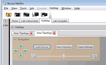
2. Click Navigation to view the options you will need to add devices to the topology.
3. Click Add Device, and select 3640 from the list of available routers.
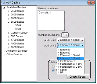
a. While the Add Device dialog box is open, select 2 in the Number of Add-ons field.
b. Select 2 Ethernet, 1 Serial as the connection types in the Add-on #1 and Add-on #2 options.
We won’t use all of these connections since we are only making a simple topology.
c. Configure a custom name if you wish in the Choose a name for your Router field, or just click Create Router to add the device with the default Router1 as the name of the device.
d. Repeat steps 3, 3a, 3b, and 3c to create a second router, Router2.
4. Click Add Device and select 3550 from the list of available switches.
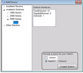
a. Click Create Switch to create Switch1, which is the default name for the device, and add it to the topology.
b. Repeat steps 4 and 4a to create Switch2.
5. Click Add Device and select PC > WinPC from the list of Other Devices.
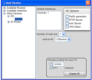
a. Click Create PC to add PC1, which is the default name for the device, and add it to the topology.
b. Repeat steps 5 and 5a to create PC2.
Now that the devices have been added to the topology, we need to connect them together. Routers can be connected together using Serial or Ethernet connections. However, in this example we will connect them using Frame Relay. Let’s begin by connecting the routers to each other, followed by adding connections to the other devices in the topology.
1. Right-click Router1, and select New Connection.
2. In the New Connection dialog box, select Frame Relay and click Connect.

3. Select Router1 in the 1st Router drop-down list and Router1’s Serial0/0 interface in the Interface drop-down list. Then assign 201 in the DLCI Destination field.

4. In the Name field, enter FR-1 to name the new device in the NetMap.
5. Repeat step 3, assigning a DLCI value of 102 to the DLCI destination for the Serial0/0 interface of Router2 as shown in the graphic below.

6. Click Apply Settings to create the new Frame Relay cloud named FR-1.
7. Move the devices in your topology around until it looks something like the graphic below.

Note: If you need to delete one of the links you create in the following steps, you should do the following:
1. Right-click one of the devices on either end of the link you wish to delete, and select Existing Connections.
2. In the Existing Connections dialog box, select the interface on the device that is part of the link you wish to delete and click Delete.

Now let’s add a serial link between Router1 and Router2 using the following steps.
Return to Frame Relay Connections
1. Right-click Router1, and select New Connection.
2. In the New Connection dialog box for Router1, select the Serial1/0 interface in the Local Interface drop-down list.

3. Select Router2 in the Remote Device drop-down list.
4. Select the Serial1/0 interface in the Remote Interface drop-down list.
5. Leave the selection for the DCE end of the link set to Router1 as shown in the graphic above.
6. Click Connect to create the link.
Now let’s add an Ethernet link between Router1 and Switch1.
Return to Frame Relay Connections
1. Right-click Router1, and select New Connection.
2. In the New Connection dialog box, select Ethernet0/0 in the Local interface drop-down list.

3. Select Switch1 in the Remote Device drop-down list.
4. Select FastEthernet0/1 in the Remote Interface drop-down list.
5. Click Connect to create the link between Router1 and Switch1.
Create the following remaining connections using the steps outlined above.
1. On Switch1, create a connection between Switch1’s FastEthernet0/2 interface and PC1.
2. On Router2, create a connection between Router2’s Ethernet0/0 interface and Switch2’s FastEthernet0/1 interface.
3. On Switch2, create a connection between Switch2’s FastEthernet0/2 interface and PC2.
Your final topology diagram should look similar to the one in the graphic below.

Now that you’ve created your topology diagram, you need to save it to the folder that will store all of the files for the lab you are creating.
1. Click NetMap on the Menu Bar, and select Save Topology.
2. Choose or create a folder on your Desktop named TestLab.
3. In the File name field, name the file TestLab.top and click Save.

4. You should receive a message that the file was saved. Click OK.
The topology file you just created could also be used in multiple labs. You would only need to copy the TestLab.top file to the folders of other labs you wish to create. This simplifies the process of creating labs because you can create a single topology file that can be used in multiple labs.
This concludes part 1 of 3, which covers creating the Lab Document and the Topology File. Stay tuned for part 2 - Creating the Loading Configuration Files and Creating the Grading Configuration Files.