By Kailin Acheson and Delana Hallstedt
As you begin the process of setting up a network, you will likely first need to figure out how to best connect the devices on the network so that communications are optimal. You might have to do a little research, planning, and organizing to make sure everything is positioned to maximize performance on that network. One good place to start is with the devices you will need to deploy. You can ask a few key questions to help point you in the right direction, such as the following:
- How many devices will be on the network?
- Are the devices all in the same room? House? Office building?
- Are the devices spread throughout a city? State? Country?
- What type of redundancy should the network have?
Two keys to any network design are the network type and the network topology. A network is the infrastructure that allows for communication between connected devices. The topology describes how the devices are connected to each other.
A network is an essential part of any multi-computer setup where the sharing of data and hardware resources is required; it facilitates communications between the computers or devices, either to each other or to devices outside their sphere. There are various network types, and the devices within these networks can be organized into various physical or logical topologies. These are the four main network types:
- Personal area networks (PANs)
- Local area networks (LANs)
- Metropolitan area networks (MANs)
- Wide area networks (WANs)
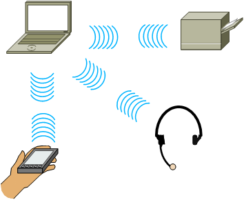
Figure 1 - Personal Area Network (PAN)
A PAN (Figure 1) can be used to connect and share data among devices that are located within a very close proximity of each other. For example, a personal computer (PC), a telephone, a printer, and a wireless headset might all be part of a home office setup using a PAN. Bluetooth and Zigbee are two technologies commonly used in a PAN setting.

Figure 2 - Local Area Network (LAN)
A LAN (Figure 2) is typically used for communications within a single group or organization and typically within a single building or site where buildings are within close proximity of each other. Two common types of LANs include Ethernet networks and Token Ring networks.

Figure 3 - Metropolitan Area Network (MAN)
A MAN (Figure 3) can be used to connect networks that reside within a single metropolitan area. For example, if a company has multiple locations within the same city, the company could configure a MAN to connect the LANs in each office together.

Figure 4 - Wide Area Network (WAN)
A WAN (Figure 4) is a network that covers a large geographical area. Often, a WAN is spread across multiple cities and even multiple countries. Computers connected to a WAN are typically connected through public networks, leased lines, or satellites. The largest example of a WAN is the Internet.
Now that you've seen the four major network types, we'll look at the main network topologies:
- Bus
- Ring/Dual-ring
- Star/Extended-star
- Partial-mesh/Full-mesh
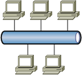
Figure 5 - Bus Topology
A bus topology (Figure 5) has a single main line to which all computers on the network are attached. Bus topologies typically use coaxial cable and have several disadvantages, such as limited cable length and a limited number of hosts. Another disadvantage to a bus topology is that a failure on the main cable affects every host on the network.
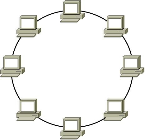
Figure 6 - Ring Topology
A ring topology (Figure 6) has a central ring of cable to which all hosts on the network connect. In a ring topology, each host is connected to exactly two other hosts. The flow of traffic in a ring topology goes in a single direction, with each node on the network handling each packet then passing it off to the next node in the ring. Similar to a bus topology (Figure 5), a failure in the ring affects every host on the network. For some simpler network environments, the ring topology has advantages over a more complex topology; one advantage is the ability to connect computers and share data without the need to purchase costly servers.
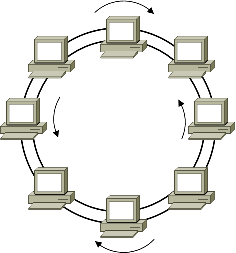
Figure 7 - Dual-Ring Topology
As compared to a standard ring topology (Figure 6), a dual-ring topology (Figure 7) has a secondary ring that allows traffic to flow in the opposite direction of the first ring so that traffic can flow in both directions at the same time. This additional ring creates a backup path for traffic; in the event that one ring fails, traffic can still flow on the other ring. Having this redundancy does improve the reliability of the ring topology; however, this is limited to protecting against damage to the cables. If one of the nodes on the ring goes down, the traffic flow will still be interrupted for the entire ring.
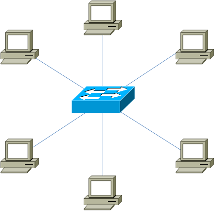
Figure 8 - Star Topology
A star topology (Figure 8) is the most common home and office network topology and is typically used on unshielded twisted-pair (UTP) Ethernet networks, but it can also be used with fiber-optic and coaxial cables. A star topology has a central connectivity device, such as a hub or a switch, to which all hosts on the network segment connect. In a very basic star topology scenario, data from one node on the network has to pass through only the central connectivity device before being sent to the intended recipient; traffic does not have to flow through all nodes in a star topology in order to reach the intended recipient. Not only can this topology improve performance, since data does not have to travel through unnecessary nodes, it also reduces the points of failure. Any given node on the network, or segment of cable, could fail and the rest of the network would still be able to communicate. However, a disadvantage of having this single point of failure is that if the central connectivity device fails, all traffic flow will stop until it has been repaired.
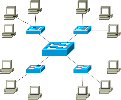
Figure 9 - Extended-Star Topology
An extended-star topology (Figure 9) offers the same performance and reliability found in a star topology (Figure 8) with the addition of the ability to cover greater distances from the central switch to the end nodes by adding repeaters or additional connectivity devices to the segments. The extended-star topology makes more sense in a larger physical environment and allows you to reduce degradation of signal in places such as the far reaches of a large corporate office. Although additional points of failure are added with each extension device, the points of failure on any given segment of the network remain fairly easy to pinpoint. If one segment becomes unavailable in an extended star topology, hosts connected to other devices in the topology will still be able to communicate. By contrast, if the central device in a star topology fails, no devices will be able to communicate on the network.
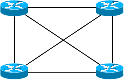
Figure 10 - Full-Mesh Topology
A full-mesh topology (Figure 10) is a very reliable network topology because of the redundancy built into it. For example, in a full-mesh network topology, each host is connected to every other host on the network. Reliability of this topology is greatly increased over other topologies because if even one segment or connection from a host to another host is down or inoperable, another path should be available for data to travel. However, even though a full-mesh topology is highly reliable, it is very difficult and expensive to implement, especially on networks that have many hosts. Thus a full-mesh topology might be suitable for a small network environment, but it would be more costly and difficult to maintain as the network grew in physical size as well as number of nodes on the network.
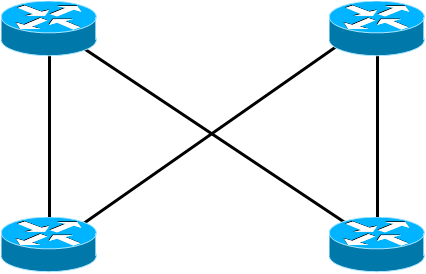
Figure 11 - Partial-Mesh Topology
Unlike a full-mesh topology (Figure 10), the hosts in a partial-mesh topology (Figure 11) are not connected to all other hosts on the network. Instead, in a partial-mesh topology, each host connects to only some of the other hosts, which reduces full redundancy yet maintains some failsafe reliability. Using a partial-mesh topology can reduce the maintenance and cost of cabling while still providing additional paths for traffic to flow in the event that one path becomes unavailable.
Now that you've seen what a few different topologies look like and read about how the different network types can be used, you might be a little more prepared to tackle your own network. For further aide in planning your network topology design, check out the Boson NetSim Network Simulator for a way to simply and reliably simulate a network or two to see what best suits your needs! We also offer exam prep software for CompTIA Network+ certificaiton and CCDA certification.